
One of the goals I wanted to do with my guitar stage setup was to be able to control everything the Adrenalinn3 pedal does with two different MIDI foot controllers. This is interesting at least, challenging at best. You can’t just combine the output of two pedals, because the Linn doesn’t know which pedal the commands came from, and even if it did, it doesn’t know what to do with them.
I looked into off-the-shelf pieces to do this, and there were a few that were close, but none of them could do what I needed without custom ROM hacking. I wasn’t really interested in that (for time constraints) so I looked into something simpler, easier, and definitely cheaper.
Enter the humble Arduino. This amazing little piece of technology takes a cheap microprocessor and packages it into a board the size of a credit card, with a voltage regulator, and input/output pins. The tools to program them are free and (mostly) easy to use, and they even make DIY add-on kits that let you expand what the board is capable of.
Since the board has a serial port, and MIDI is essentially a serial communication protocol, we can input and output MIDI messages with it. Sparkfun makes a MIDI add-on board (called a “shield”) that adds properly optoisolated MIDI hardware ports, some switches, and a couple of pots and LED’s.
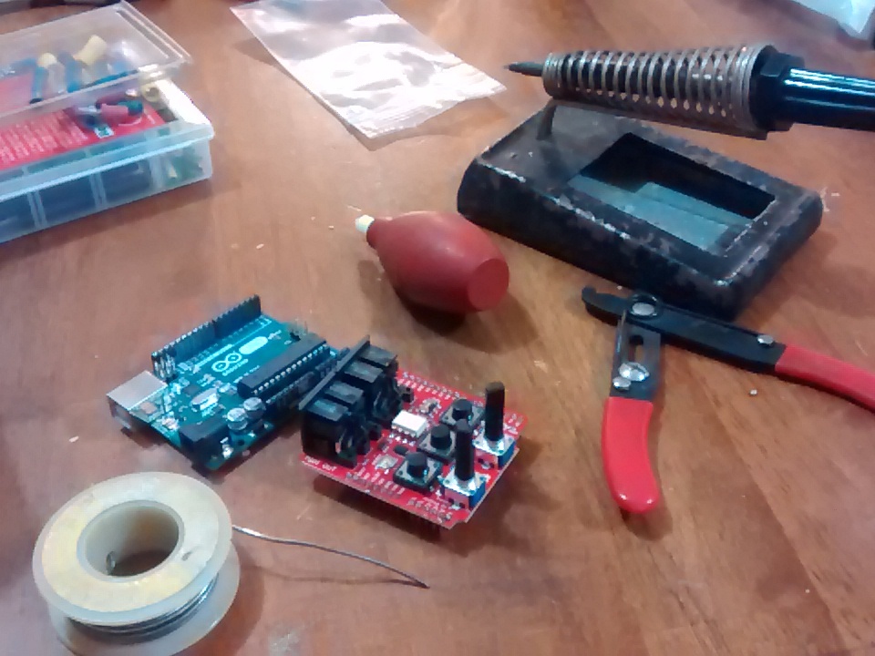
After soldering the board together, I plopped it onto the Arduino, downloaded the MIDI libraries, and started coding!
There’s tons of documentation on how to program Arduino boards with the regular functions. There’s not much info or examples on how to do MIDI programming, though. I did manage to pull bits and pieces of code from different examples, and was able to figure out how to get what I needed.
Basically (geek warning here) when I get messages from a controller, I want it to simply pass through everything except Program Change messages. Those PC messages need to have another Control Change message inserted before and after each one. This changes the “preset” mode on the Linn pedal… normally, a PC message would change either the drumbeats, or effect presets, or both at the same time, but there’s no way to separately control drumbeats and effects (at the same time) with PC messages. The Linn doesn’t know which controller sends the message, and doesn’t allow you to use different messages to change the 2 different sections independently.
If we send a “Bank Change” message, we can use that to change the Linn’s preset mode, i.e. which section the PC changes will affect. After the PC message goes through, we send another Bank Change to switch it back.
Now, excuse my horrible coding skills… I’m not a programmer. I understand the concepts well, but I have little patience to learn syntax and whatnot. It requires an attention to detail I just don’t have. Small stuff like this, though, I can do.
The code looks like this (pardon the unused references to switches and pots, they’re in there in case I want to do something with them later):
#include <MIDI.h>

// Message filter for the Roger Linn "Adrenalinn 3" pedal.

// To change presets and drum patterns with 2 different controllers,

// we search for PC on channel 1, and insert Bank Change messages before and after

// to switch to Preset mode and back. Any other PC messages get passed through.

// Set the Linn to recieve on "All" and set the "PROG CHNG" setting to "DR0"

// Channel 1 PC changes the presets, and any other channel PC changes drum patterns.

MIDI_CREATE_DEFAULT_INSTANCE();

#define LED 13 // LED pin on Arduino Uno

#define LED2 6 // LED on MIDI board

#define LED3 7 // LED on MIDI board

#define switch1 2 // 1st Switch

#define switch2 3 // 2nd Switch

#define switch3 4 // 3rd switch

#define POT_1 A0 // Potentiometer 1

#define POT_2 A1 // Potentiometer 2

//Variables

bool switch1LastState = 0;

bool switch1CurrentState = 0;

bool switch2LastState = 0;

bool switch2CurrentState = 0;

bool switch3LastState = 0;

bool switch3CurrentState = 0;

void setup()

{

pinMode(LED, OUTPUT);

pinMode(LED2, OUTPUT);

pinMode(LED3, OUTPUT);

pinMode(switch1,INPUT_PULLUP);

pinMode(switch2, INPUT_PULLUP);

pinMode(switch3, INPUT_PULLUP);

pinMode(POT_1, INPUT);

pinMode(POT_2, INPUT);

MIDI.begin(MIDI_CHANNEL_OMNI); // Launch MIDI and listen on all channels

digitalWrite(LED, HIGH);

digitalWrite(LED2 ,HIGH);

digitalWrite(LED3, HIGH);

MIDI.turnThruOff();

}

void loop()

{

switch1CurrentState = digitalRead(switch1);

switch2CurrentState = digitalRead(switch2);

switch3CurrentState = digitalRead(switch3);

// if (switch1CurrentState = 1 )

// {

// digitalWrite(LED2, LOW);

// delay(1000);

// digitalWrite(LED2, HIGH);

// switch1CurrentState = 0;

// }

if (MIDI.read()) // If we have received a message

{

switch(MIDI.getType()) // Get the type of the message we caught

{

case midi::ProgramChange: // If it is a Program Change,

digitalWrite(LED2,LOW);

if (MIDI.getChannel() == 1)

{

MIDI.sendControlChange(32, 0, 1);

delay(10);

MIDI.sendProgramChange(MIDI.getData1(), 1);

delay(10);

MIDI.sendControlChange(32, 2, 1);

}

else

{

MIDI.sendProgramChange(MIDI.getData1(), MIDI.getChannel());

delay(0);

}

digitalWrite(LED2,HIGH);

break;

// Controller changes get passed through. I added code to convert an on/off 0-127 CC to 64-127 (for effects that have -100 to +100 range)

case midi::ControlChange :

digitalWrite(LED3,LOW);

if (MIDI.getData1() == 64)

{

if (MIDI.getData2() == 0) MIDI.sendControlChange(64, 63, MIDI.getChannel());

if (MIDI.getData2() == 127) MIDI.sendControlChange(64, 97, MIDI.getChannel());

}

else

{

MIDI.sendControlChange(MIDI.getData1(), MIDI.getData2(), MIDI.getChannel());

}

digitalWrite(LED3,HIGH);

delay(0);

break;

// Though in theory clock does work, I couldn't get the PC/CC's to work with them so the clock messages are commented out.

// Feel free to experiment.

// case midi::Clock:

// MIDI.sendRealTime(MIDI_NAMESPACE::Clock);

// break;

// case midi::Start :

// {

// MIDI.sendRealTime(MIDI_NAMESPACE::Start);

// }

// break;

// case midi::Stop :

// {

// MIDI.sendRealTime(MIDI_NAMESPACE::Stop);

// }

// break;

default:

break;

}

}

}
You’ll notice the CC commands go through untouched, while PC commands get a “CC 32, 0, 1” inserted before and “CC 32, 2, 1” appended after. I kept having trouble with it, and included code to pass through Clock messages… but it wouldn’t pass through PC or CC commands once the clock was running. I ended up commenting that part out, and just filtering the PC and CC commands. I will have to use a hardware MIDI merge to make it work together, but I may play with it some more later and see if I can get it to work more smoothly. I suspect the Arduino just couldn’t time the messages correctly, even though it looked like everything was passing through on the other end. Oh well. It does what I want.
Now that I’ve got the setup worked out, I will be going through and making music with it. I mean, that’s the whole reason I built it in the first place!